CFD DEPARTMENT
JETWINGS TECHNOLOGIES


CFD ANALYSIS OF AERODYNAMIC PERFORMANCE VALIDATION FOR RECON UNFINED DRONE
Introduction:
Usually any scientific study starts from what others have already achieved. Flapping wing study is not an exception, so in this chapter existing devices, which have been developed and manufactured by many companies for civilian or military sakes, will be presented. The overview on such vehicles will be organized by sections according to the nature of the machines: a brief summary on fixed wing UAVs, then MAVs and UAVs based on flapping wing technology.
Fixed wing UAVs are just the point of reference for more complicated devices, since they come from a widely explored field of research in flight dynamics. They are put in motion by a propeller and essentially based on the geometry of small airplanes. These objects are basically built with common modelling materials such as balsa wood, fiber glass tape or EPP (expanded polypropylene), which has high resilience properties and very low weight.
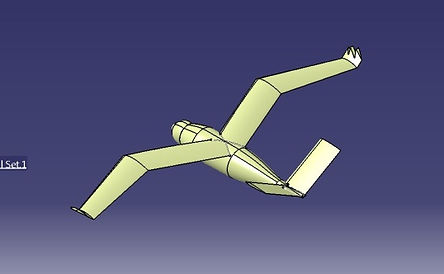
Fly bird Design:
The Fly bird design is modeled using CATIA V5, a multi-platform CAD/CAM/CAE commercial software suite. It is a feature-based, parametric solid modeling design tool used to create fully associative 3D solid models, with or without constraints, while using automatic or user-defined relations to capture the design intent. CATIA graphically displays the feature based structure and other non-graphical data of the model in the form of a specification tree.
This contains three separate parts, fuselage, tail and wing. These three are designed separately and assembled in assembly work bench. Fuselage part is fixed and wing and tail is placed on fuselage top. The bottom-up method is prepared for assembling process. Final assembled product is saved in .iges file format.
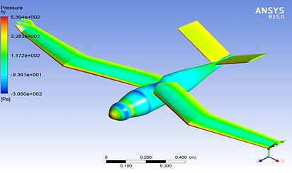
Analysis Description:
The above figures show that the meshing and Pressure distribution over on model. The model analyzed with the different Angle of Attack. The fly bird model fuselage, wing and tail are designed by using CATIA-V5 and analysis process is done for different angle of attack. The pressure and velocity contours are obtained, force values are tabulated above. From this analysis the wing and fuselage lift force are calculated. In this model wing is totally different from other UAV wings and wing is placed at certain angle to fuselage. This type of wing is mostly used in flapping wing model. For zero angle of attack wing produce 35.9N and fuselage produce 4.13N lift. Due to increase of angle of attack wing lift also increased. For 16 degree of angle of attack 57.2N lift is created in wing and less drag. It gives better lift compare to other models. This model stall is above 20 degree. So it gives better performance. Total lift range is 23N to 59N.