CFD DEPARTMENT
JETWINGS TECHNOLOGIES


REGENERATIVE COOLING IS ONE OF THE MOST WIDELY APPLIED COOLING TECHNIQUES USED IN LIQUID PROPELLANT ROCKET ENGINES
Introduction:
REGENERATIVE COOLING is one of the most widely applied cooling techniques used in liquid propellant rocket engines. It has been effective in applications with high chamber pressure and for long durations with a heat flux range 1.6 to160 MW/m2. Regenerative cooling of a liquid propellant rocket engine consists of a balance between the energy rejected by the combusted gases and the heat energy absorbed by the coolant. The energy absorbed by the coolant is not wasted; it augments the initial energy content of the propellant prior to injection, increasing the exhaust velocity slightly (0.1 to 1.5%). Therefore thermal energy is recovered in the system.
Basically there are three domains in a regeneratively cooled rocket engine; gas domain (combusted gases), liquid domain (coolant) and the solid domain (thrust chamber wall). The heat transfer analysis in regenerative cooling are simply based on convection and radiation heat transfer for gas domain, conduction heat transfer for solid domain and convection heat transfer for liquid domain. Heat transfer from the outer surface of thrust chamber to the environment can be neglected and the outer surface wall can be assumed as adiabatic. To simplify the gas side and coolant side heat transfer analysis, many correlations are developed to calculate the heat transfer coefficients. However, as the complexity of the cooling system increases so do the penalties incurred with it, such as added equipment, piping, electronics, and a notable increase in weight. The focus here will be to use (CFD) software to analyse the coolant performance characteristics of a notional small scale liquid propellant rocket engine with a regenerative/dump cooling system under operating condition.
Geometry and Mesh:
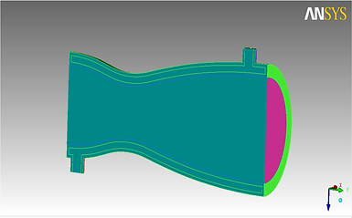
Fig: Symmetric design of Full Nozzle. The designed have bypass for cold fluid flow regenerative cooling.
Fig: Solid Meshing in symmetric Nozzle design.
Analysis:
The analysis done for two design model such as Single inlet and outlet, Double inlet and outlet. Two different kinds of Fluids (Cold Air, Kerosene) are used for cooling.
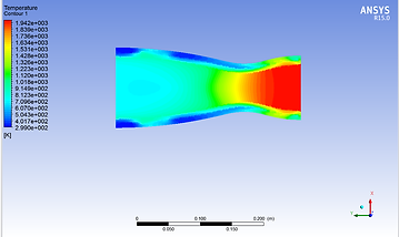
Fig: Temp Contour for Coolant Air with single inlet and single outlet configuration.
Fig: Temp Contour for Coolant kerosene with single inlet and single outlet configuration.
Conclusion:
Finally the result concluded that the coolant air transferred more heat compare with kerosene. Multi inlet and outlet thruster showing a drastic decrease in temperature along the bottom of the thruster nozzle and a more even temperature distribution throughout.