CFD DEPARTMENT
JETWINGS TECHNOLOGIES


CFD ANALYSIS ON AERODYNAMIC BEHAVIOUR FOR A FLAPPING WING TO UAV APPLICATION
Flapping wing UAVs
The main feature of the Unmanned Aerial Vehicles is the possibility to control them remotely or even program them and let them act without the human presence. Their use is particularly well fitted in dangerous places or operations; not only in military missions in war sceneries, but also civil tasks in chemically or radioactively compromised areas. Especially in the first case, the model appearance and dynamics have to be as close as possible to an actual bird, according to the place of use and local distribution of certain species of animal. Since this type of robots are the most technologically developed so far, they are supplied with complicated mechanical train able to reproduce the flapping motion of the wing considering many of the joints of a real bird wing. The large field of application justifies fluid dynamics and aerodynamics studies in order to have realistic simulations before the actual manufacturing of the prototypes. Since, our project mainly concentrated on flow behaviour over on Flapping wing by using CFD.
Geometry:
Wing Configuration:
-
Rectangular
-
Tapper
-
Swept wing
Aerofoil Used:
-
E452
-
Selig 1020
-
Selig 1223
User Defined Function:
The so called UDFs are the programming codes which have the role to control to motion of the moving surfaces. They are usually written in C language and they need some reference points into the mesh. For this reason, all the reference systems of the CAD drawing, the solid model and the mesh have to match on the same point. This type of UDF is generally fitted to include motions about three different axes: roll, and pitch. The frequency of the flapping is another variable which can be adjusted as preferred. However, this program is suited to move a rigid wing.
Analysis Description:
CFD simulations were first carried out for the Aerofoil E472 wing using ANSYS Fluent 15 solver with k-ε turbulence model at Velocity 12 m/s, Flapping Amplitude 60, Feathering Amplitude 30 and Frequency 20 Hz. The simulations were then carried out on the different wing configurations for various Aerofoils like Selig 1020 and Selig 1223. In this flight condition, strong turbulence builds around the wing. The pressure coefficient (CP), Lift coefficient (CL) and Drag coefficient (CD) were extracted for all configurations.
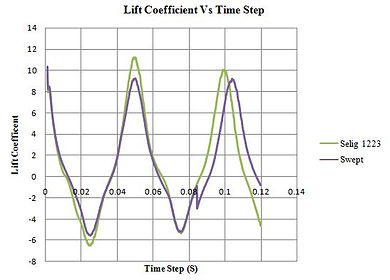
Fig2. Result Comparison
Fig 3. Stream lne contour shows that absence of wing tip vortices in Selig 1223 wing Tip
Result:
The result from all configuration compared and finally Tapper wing and Swept configuration selected for final analysis. The above graph shows that comparison between Tapper wing and Swept wing configuration. The mean CL and CD value for Swept wing is 1.8 and 0.7 respectively. The CL value of Swept is 33% more than tapper wing configuration and CD value is 17% less than tapper wing configuration. This because of the Selig 1223 Swept wing have less turbulence and wing tip vortices controlled by Eagle wing shape. The finally result concluded that the Swept wing configuration give best aerodynamic performance for Flapping wing motion.